This website has been archived from TrainWeb.org/girr to TrainWeb.US/girr.
Aristo 0-4-0 Switcher Tips
 The Aristo 0-4-0
is a nice little engine but it has a major problem. On most units,
the four driver wheels get dirty very quickly and when that
happens, the thing doesn't run at all. Aristo has addressed this
problem with a wheel change, see below. With clean wheels it pulls
fairly well considering its light weight. It is quiet and smooth
and doesn't derail often, at least on large radius track. I have
had some difficulties with it picking the frog on 1200 series
turnouts.
The Aristo 0-4-0
is a nice little engine but it has a major problem. On most units,
the four driver wheels get dirty very quickly and when that
happens, the thing doesn't run at all. Aristo has addressed this
problem with a wheel change, see below. With clean wheels it pulls
fairly well considering its light weight. It is quiet and smooth
and doesn't derail often, at least on large radius track. I have
had some difficulties with it picking the frog on 1200 series
turnouts.
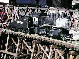
The Aristo 0-4-0 is apparently modeled after the Pennsylvania Railroad A5 Class switcher. The model matches the size and overall appearance of this class well.
The model is nominally 1:29 scale and scales out pretty close. The model has fair detail and runs smoothly and quietly as long as the wheels are clean. It will run a much faster than scale speeds. Switchers were not known for high speed operation, but this little bugger will do 100 mph if you crank up the track voltage.
Contents
- Wheel Issues
- Stock Sound System
- Smoke System
- Mounting Kadee Couplers
- Disassembly and Reassembly of the 0-4-0
- DCC Installation in the 0-4-0
- Dallee Sound System Installation
- Installing a Zimo DCC Decoder in the 0-4-0
 13 Jan 01
Wheel Issues
The main weak point of the 0-4-0 is its wheels. They are some kind of casting and the behave similarly to the wheels on the Pacific, in other words, they get dirty REAL fast. I don't know what the specific problem is but they just sweep up crud and power pickup gets flaky.
You can improve the power pickup by wiring the tender across to the loco to add 8 more wheels of power pickup. This helps a lot, but the tender wheels are made of the same stuff and they get cruddy too.
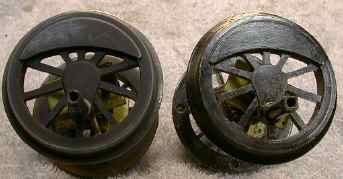 Aristo sent me a set of new wheels for
evaluation. Lewis Polk said that the wheels are made with the same
process as the wheels on the new ball bearing truck diesel bricks.
The wheels came assembled with the bushings/power pickups and the
front one came already greased inside its gearbox. The old wheels
are a chemically blackened casting with a high copper content
(probably a bronze). I do not know the composition of the new
wheels, but they appear to be anodized instead of blackened. The
old wheels, especially the spokes are flat black in color. The new
wheels are dark gray brown with a moderate sheen.
Aristo sent me a set of new wheels for
evaluation. Lewis Polk said that the wheels are made with the same
process as the wheels on the new ball bearing truck diesel bricks.
The wheels came assembled with the bushings/power pickups and the
front one came already greased inside its gearbox. The old wheels
are a chemically blackened casting with a high copper content
(probably a bronze). I do not know the composition of the new
wheels, but they appear to be anodized instead of blackened. The
old wheels, especially the spokes are flat black in color. The new
wheels are dark gray brown with a moderate sheen.
After 10 minutes of running, the anodization on the treads of the new wheels was substantially scrubbed. After an hour, it was gone. This did not seem to have any impact on the power pickup, which remained very steady the whole time. After an hour of running with the old wheels, the engine would have been essentially nonfunctional. With the new wheels, the headlight was not even flickering. The wheel treads are still shiny and clean without a hint of the nonconductive crud that used to coat the wheels.
I do not know Aristo's plans for providing the new wheel assemblies as replacement parts, but they ought to make them available. This is a significant improvement.
Wheel installation instructions.
- Place the engine on its side and remove the screw that holds the connecting rod to the front driver. It may be behind the crosshead so that you may have to rotate the wheels some to gain access to the screw.
- Remove the screw that holds the valve gear to the crank on the rear driver.
- Remove the screw that holds the connecting rods and the valve gear crank from the rear driver. Pull off the valve gear crank and the connecting rod. Note the orientation of the connecting rod.
- Turn the engine over and do the same thing to the other side. Note that the connecting rods are not identical and you have to get them back on the same way that you took them off.
- Prop the engine cab roof on a couple of blocks of wood so that the engine is supported by the cab roof at two points and the smokestack at the third point.
- Remove four screws that hold the engine bottom cover in place and remove the bottom cover.
- Unsolder two black wires that go to tabs on the front gearbox.
- Unsolder two white wires that go to tabs on the rear wheel bushings. Note which side these went to.
- Pull out the rear wheel assembly. Note that the short end of the bushing goes into the engine frame.
- Pull up on the gearbox to rotate the gearbox and the motor upward enough to remove the front gearbox assembly.
- Check to see that the gear in the new front gearbox assembly is greased and grease it if it needs it. Apply some oil to the front axle bushings.
- Tin the metal power pickup tabs so that it will be easier to solder wires to them later.
- Install the new gearbox over the end of the motor and push the assembly back down in place. Note that the rear end of the motor shaft must fit within the thrust bearing at the rear of the motor block.
- Resolder the two black wires to the front gearbox tabs.
- Tin the tabs on the rear wheel bushings.
- Grease and oil the rear drive gear and axle bearings.
- Install the rear wheel assembly. Note that it will fit properly only one way, if it won't mesh with the worm gear, you've got it upside down.
- Solder the two white wires back to the tabs on the rear wheel bushings.
- Replace the connecting rods and valve cranks.
- Apply enough power to the loco to get the wheels to turn to make sure that the connecting rods do not bind. If they do, lift the rear axle assembly a little and rotate it one tooth and recheck for binding.
- Replace the bottom cover.
Stock Sound System
The Slopeback Tender comes with a sound system installed. This system has been much derided, but under the right conditions it isn't too bad.
The system chuffs fairly well but that's all it does. The sound system relies on the Aristo PWC system to work properly. Without PWC, the sound system doesn't get enough voltage off the track to work and can howl, growl, or screech terribly at low speed. On pulse power packs (such as MRC packs) it will hum and buzz. With PWC, it may occasionally make awful sounds but only at very slow speed. Unlike the Pacific's Long Tender, there is no provision for connection of a battery to allow the pack to work without PWC.
The volume control for the chuff is accessed by lifting the coal load from the rear. The water hatch slides back to unlatch the coal load.
The chuff trigger is a Hall effect device mounted above a tender axle. A doughnut shaped magnet rides against a rubber roller on the axle. The Hall effect device is mounted next to the magnet. If the chuff isn't working right, make sure that the rubber roller is clean and that the Hall effect device is RIGHT NEXT to the magnet. Even when it is working, the chuff rate is about half of the prototypical rate of 4 chuffs/turn.
After the rubber roller gets old and hardens up some it doesn't provide enough friction to turn the magnet reliably. After much fussing and fiddling, I finally tried to renew the roller surface with a coating of contact cement, AND IT WORKED! Pull the wheelset with the roller from the truck by flexing the truck sideframe slightly and then paint a layer of contact cement on the roller. Rubber cement would probably work too. Let it dry for about an hour and reinstall the wheelset. I do not know how long this patch will last, but even if it fails after awhile, it would be easy enough to do it again.
[ Top ]Smoke System
The 0-4-0 comes with a smoke generator that is driven by an air pump in the left cylinder. The unit puffs smoke in time with the drivers. The pump can be a little stiff when new causing the engine to run unsteadily at low speed. However, after a few hours of running, the pump will loosen up and low speed operation will smooth out. If you should remove the shell, be sure to reconnect the plastic hose back to the smoke unit when the shell is replaced. You can easily see and access the hose by popping off the smokebox cover.
[ Top ]Mounting Kadee Couplers
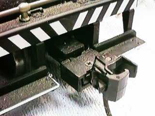 A
Kadee #831 coupler can be mounted directly in place of the supplied
Aristo knuckle coupler, however the rear step must be cut to clear
the coupler box. Cutting right next to the step supports will
provide enough clearance for running on 8' diameter curves. To
accommodate 4' diameter curves, more of the step and the inside two
step supports would have to be removed and new step supports
fabricated from strip styrene.
A
Kadee #831 coupler can be mounted directly in place of the supplied
Aristo knuckle coupler, however the rear step must be cut to clear
the coupler box. Cutting right next to the step supports will
provide enough clearance for running on 8' diameter curves. To
accommodate 4' diameter curves, more of the step and the inside two
step supports would have to be removed and new step supports
fabricated from strip styrene.
A Kadee #831 can also be mounted on the front of the 0-4-0 directly by using the existing hole and a Kadee supplied screw. A couple of the black Kadee supplied shims might be required to set the coupler at the right height.
[ Top ]
Taking The 0-4-0 Apart
- The Top Side
- Prop or cradle the engine upside down
- Remove two small screws under the cab
- Remove one small screw up under the engine just in front of the motor block
- Pull off the boiler and cab. Be careful so that you don't damage the wires leading to the smoke unit and headlight.
- Reassemble in the reverse order. Pop off the smokebox cover and make sure that the plastic tube that comes up from the frame fits in the barb on the smoke unit.
- The Bottom Side
- Prop or cradle the engine upside down
- Remove 4 screws on the bottom cover and remove it.
- Reassemble in the reverse order.
- The Tender
- Prop or cradle the tender upside down
- Remove 4 screws on the bottom cover and remove it by the front first, there are clips at the back.
- Reassemble in the reverse order.
DCC Installation in the 0-4-0
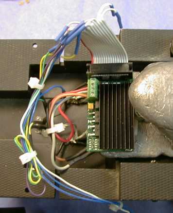
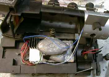 Installation of DCC in the 0-4-0 is a piece of cake. All the
connections necessary are on the top of the frame so that only the
shell needs to be removed. I installed a Digitrax DG580L crosswise
across the rear of the lead weight with a piece of double back foam
tape. This decoder also has a small heat sink screwed to it. Even
though the engine is small, the decoder can get quite hot without a
heat sink of some kind.
Installation of DCC in the 0-4-0 is a piece of cake. All the
connections necessary are on the top of the frame so that only the
shell needs to be removed. I installed a Digitrax DG580L crosswise
across the rear of the lead weight with a piece of double back foam
tape. This decoder also has a small heat sink screwed to it. Even
though the engine is small, the decoder can get quite hot without a
heat sink of some kind.
There are two terminals screwed to the frame inside the firebox. There is a red wire leading down from one and a couple of black wires leading down from the other. The red wire and one of the black wires go to the motor and must be disconnected. The red wire is easy, you'll have to make a measurement to determine which black wire to use. Once all three wires are off the terminals, use an ohmmeter to see which black wire has about 7 ohms to the red wire. Solder the other black wire back to the terminal it came from.
Solder the black decoder wire to the terminal where the red motor wire went. Solder the red decoder wire back to where the black motor wire went. Solder the gray decoder wire to the red motor wire. Solder the orange decoder wire to the black motor wire and insulate all the connections.
I also wired the headlight between the blue decoder wire and F0 (white). I cut the headlight wires from the loco wiring and insulated the cut ends of the loco wiring . The decoder wires will reach forward to the headlight wires. I also connected the firebox light to the decoder between the blue decoder wire and the brown decoder wire (F3) and programmed the FX function in the decoder to random flicker to simulate a flickering firebox.
The tender light is wired to the F0(R) function of the decoder.
The DCC signal on the track effected the stock 0-4-0 sound system a little. There is a slight buzz due to the DCC signal leaking into the sound system, but it is not very loud and it can't be heard from more than a couple of feet away. I expected worse. The buzz went away when I put a Dallee system into the tender.
Since track power is available all the time, the sound system may not shut down when the engine stops. You may have to tweak the engine forward or backward some to get the chuff to stop blowing. It may be possible to sense the presence of motor pulses and shut down the system when the pulse train stops. This might make an interesting future project.
 Eventually the motor noise made by the DG580L got to me. Also it
started to behave strangely sometimes so I changed it out to an MRC
AD320 as an experiment since the 0-4-0 was so noisy. This
inexpensive decoder ($30) makes almost as much noise as the
Digitrax decoder, but at least it runs properly all of the time.
The AD320 has only four function outputs, F0 (forward and reverse),
F1 and F2. I wired the headlights, bell and whistle. I left the
firebox light disconnected.
Eventually the motor noise made by the DG580L got to me. Also it
started to behave strangely sometimes so I changed it out to an MRC
AD320 as an experiment since the 0-4-0 was so noisy. This
inexpensive decoder ($30) makes almost as much noise as the
Digitrax decoder, but at least it runs properly all of the time.
The AD320 has only four function outputs, F0 (forward and reverse),
F1 and F2. I wired the headlights, bell and whistle. I left the
firebox light disconnected.
[ Top ]
Dallee Sound System Installation
Since I had already installed DCC in the 0-4-0, I decided to try a Dallee steam sound system because it was relatively inexpensive, about $125 including an IR chuff sensor. Also the Dallee system integrates fairly well with DCC decoders. The Dallee steam sound system doesn't have the sound quality of the more expensive systems but it is good enough as long as the chuff rate doesn't get too high. At high chuff rates, the chuff simply fades away. Dallee claims that this is the way it supposed to be, but I would expect the chuffs to merge into a steady roar instead of fading away completely. The system that I choose was for a PRR K4 since it seemed to be the closest to the PRR A5 0-4-0 prototype. All the Dallee chuff sounds are the same, the only thing that differs is the whistle sound.
I have subsequently done an installation of a Soundtraxx Sierra in another slopeback tender. This system sounds much better and integrates with DCC well also, but it requires the addition of some additional parts. Integration of the Sierra and DCC is described in my Shay Tips page.
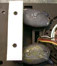 After the
stock sound board was removed, the first order of business was to
find a place to mount the Dallee board. The Dallee board just fit
crosswise in the tender body so I cut a small piece of styrene and
mounted it to the two posts that held the original board. The
Dallee board was then stuck down to this piece of plastic with the
supplied foam tape. This placed the Dallee board so that the
controls on the board can be accessed through the coal load.
After the
stock sound board was removed, the first order of business was to
find a place to mount the Dallee board. The Dallee board just fit
crosswise in the tender body so I cut a small piece of styrene and
mounted it to the two posts that held the original board. The
Dallee board was then stuck down to this piece of plastic with the
supplied foam tape. This placed the Dallee board so that the
controls on the board can be accessed through the coal load.
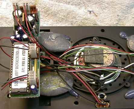 The Dallee board
was wired to the power pickups in the tender and to the existing
itty bitty speaker. The floor of the tender is clearly sized for a
2.5" speaker, but this little speaker is mounted instead. Dallee
supplies only a 1" speaker (intended for use in HO) so I elected to
retain the existing speaker. I'll get a better one later because
the system clearly needs it. The horn and whistle command pins are
wired forward to the decoder in the engine on two pins of a 5 pin
Molex type connector. Two other pins share track power between the
tender and the engine. The fifth wire is used to wire the rear
headlight to the decoder. Power for the rear headlight is derived
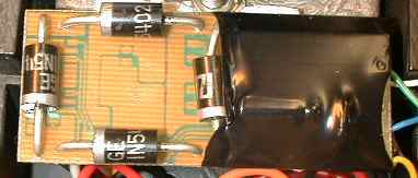
from two diodes connected to the power pickups in the tender. The
two diodes simulate the blue wire from the decoder which I couldn't
bring back to the tender because I ran out of pins.
The Dallee board
was wired to the power pickups in the tender and to the existing
itty bitty speaker. The floor of the tender is clearly sized for a
2.5" speaker, but this little speaker is mounted instead. Dallee
supplies only a 1" speaker (intended for use in HO) so I elected to
retain the existing speaker. I'll get a better one later because
the system clearly needs it. The horn and whistle command pins are
wired forward to the decoder in the engine on two pins of a 5 pin
Molex type connector. Two other pins share track power between the
tender and the engine. The fifth wire is used to wire the rear
headlight to the decoder. Power for the rear headlight is derived
from two diodes connected to the power pickups in the tender. The
two diodes simulate the blue wire from the decoder which I couldn't
bring back to the tender because I ran out of pins.
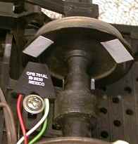 The sound board
can control the chuff rate based on motor voltage or it can use an
external switch or optical sensor to sequence the chuff. Since I
was short of pins already and couldn't bring the motor voltage back
to the tender, I elected to use the Dallee #853 optical chuff
sensor. This device projects an IR beam and detects reflections
from alternating white and black surfaces. Since the tender wheel
is almost exactly 3/4 of the size of the drivers, three white spots
on the inside wheel rim result in a nearly correct 4 chuffs per
driver turn. The optical sensor is fairly sensitive to distance
from the wheel rim, too close or too far and it won't work.
Fortunately, it fit nicely on the bottom of a truck. Eventually, I
reduced the number of stripes on the wheel back to reduce the chuff
rate so that the system had a hope of keeping up. It now chuffs
twice per tender wheel turn or about three times per driver
turn.
The sound board
can control the chuff rate based on motor voltage or it can use an
external switch or optical sensor to sequence the chuff. Since I
was short of pins already and couldn't bring the motor voltage back
to the tender, I elected to use the Dallee #853 optical chuff
sensor. This device projects an IR beam and detects reflections
from alternating white and black surfaces. Since the tender wheel
is almost exactly 3/4 of the size of the drivers, three white spots
on the inside wheel rim result in a nearly correct 4 chuffs per
driver turn. The optical sensor is fairly sensitive to distance
from the wheel rim, too close or too far and it won't work.
Fortunately, it fit nicely on the bottom of a truck. Eventually, I
reduced the number of stripes on the wheel back to reduce the chuff
rate so that the system had a hope of keeping up. It now chuffs
twice per tender wheel turn or about three times per driver
turn.
 I had another problem with
the Dallee that I found annoying. It would blow the whistle for no
obvious reason at random times. I had this same problem in the RS-3
installation, so I think that the sound system is at fault. In any
event, to solve this problem I installed an optoisolator and the
problem went away. The bell didn't have the same problem, but if it
starts to flake out, I'll isolate it too.
I had another problem with
the Dallee that I found annoying. It would blow the whistle for no
obvious reason at random times. I had this same problem in the RS-3
installation, so I think that the sound system is at fault. In any
event, to solve this problem I installed an optoisolator and the
problem went away. The bell didn't have the same problem, but if it
starts to flake out, I'll isolate it too.
[ Top ]
Installing a Zimo DCC Decoder in the 0-4-0
 This little loco has now
had three different DCC decoders installed in it. The original
Digitrax DG-580L failed and got flakey. Also the low PWM frequency
caused an enormous amount of motor noise. It was replaced by an MRC
AD320 decoder which also made a lot of motor noise. The noise was
just too much for me so I installed a Zimo MX65S/N decoder. This
one switches at 16 kHz and is nearly silent. It also worked better
overall than either of the two previous ones. There were no changes
required to the Dallee sound installation.
This little loco has now
had three different DCC decoders installed in it. The original
Digitrax DG-580L failed and got flakey. Also the low PWM frequency
caused an enormous amount of motor noise. It was replaced by an MRC
AD320 decoder which also made a lot of motor noise. The noise was
just too much for me so I installed a Zimo MX65S/N decoder. This
one switches at 16 kHz and is nearly silent. It also worked better
overall than either of the two previous ones. There were no changes
required to the Dallee sound installation.
The Zimo MX65S is an upscale decoder. It has a 3 amp average capacity, plenty for this loco, and back-emf motor control. The 0-4-0 had a tendency to run away on downgrades so the back-emf control helps keep the loco speed a little more constant. The MX65S will do just about everything that any other decoder will do except it does not have special effects on the function outputs.
Schematic of a Zimo DCC Installation in an Aristo 0-4-0
As delivered, the Zimo decoder needs a considerable amount of programming to get it working properly. When I first fired it up, the engine ran terribly. The Zimo comes set to a low PWM frequency with very high gain in the back EMF control. I needed to change the back EMF setting (CV58) to about 128 (decimal) and set CV9 to 0 to get the engine to run smoothly and quietly. It also needed tweaks to the start, mid and max voltages. The 0-4-0 tends to run really fast, so it is desirable to set the max speed to about 128 (decimal) as well with a mid point set at about 60 (decimal) to control the maximum speed of the loco.
The Zimo decoder went in pretty easily, the only hassle is function wiring. The function connections are a dual row of pins that you have to count to locate. A ribbon cable with an appropriate connector was supplied by Tony's Train Xchange, but since I had color coded wires already in the loco, I cut the ribbon quite short and spliced into it. Unused wires in the ribbon were capped off with a short length of shrink tube.
Zimo numbers their functions differently from the Digitrax, Lenz and NCE "standard" that I am used to. The table below lists the connections to the decoder along with the Digitrax function numbers and the wire colors that I used. The color column really has meaning only to me but I figured that recording them here would help me the next time I dug into the loco.
| Actual Function | Zimo Pin | Zimo Function Name | Digitrax Function Name | Wire Color |
|---|---|---|---|---|
| Front Headlight | 6 | FLf | F0F | White |
| Rear Headlight | 11 | FLr | F0R | Yellow |
| Bell | 14 | Function 2 | F1 | Green |
| Whistle | 7 | Function 3 | F2 | Purple |
| Firebox Light | 13 | Function 4 | F3 | Brown |
| Not Used | 9 | Function 5 | F4 | N/A |
| Not Used | 12 | Function 6 | F5 | N/A |
| Not Used | 8 | Function 7 | F6 | N/A |
This page has been accessed
© 1997-2001 George Schreyer
Created Oct 12, 1997
Last Updated Jan 13, 2001