This website has been archived from TrainWeb.org/tubeprune to TrainWeb.US/tubeprune.
|

|
||||||||||||||||||||||||||||||||||||||||||||||||||||


| Car | Weight | Seats | Equipment | ||||||
| DM | 27.2 tons | 38 | Cab | Shoes | Traction Package | Emergency coupler� | Motor Alternator | Batteries | |
| T | 26.2 tons� | 38 | Compressor | ||||||
| UNDM | 18.2 tons | 38 | Shunting controller | Shoes | Traction Package | Auto coupler | Motor Alternator | Batteries | |
| �Auto-coupler on double-ended DM cars. � Trailer in double-ended unit weighs 26.84 tons | |||||||||
Although the cars were longer than the traditional Underground design, the arrangement of doorways was the same. This is because the small body profile required by tube tunnels restricts the floor height. This in turn requires that the wheels intrude into the underframe construction over the bogies. Doors cannot be located at these positions so the openings for the wheels are covered by longitudinal seats. Each car has four doorways on each side with a single leaf sliding door at each end and two double doorways between. The doorway opening is the standard 1372mm (4ft 6ins).
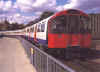
 Fig 10: 1973 Tube Stock UNDM with safety barrier at Rayners Lane.
Click on the image for the full size view.
One recent modification of the 1973 Tube Stock, which has also been applied to other lines, is the provision of inter-car safety barriers. These first appeared in 1997 and were a response to the occasional accidents where passengers - usually those suffering from the effects of alcohol or drugs - have fallen between cars. The barriers are made of black canvas and are hung on brackets fitted to the outer corners of the car body. They are coupled between cars on sprung attachments to allow transition on curves without creating a gap or tearing. They look dreadful and have become something of a maintenance problem.
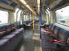
 Fig 11: 1973 Tube Stock refurbished driver's
desk
Fig 11: 1973 Tube Stock refurbished driver's
desk
Click on the image for the full size view.
To the Top of this Page
Back to the Rolling Stock Page
Innovations
The 1973 Tube Stock had a number of radically new systems never seen on the Underground before. These included electrical control of emergency braking (thus eliminating the brake pipe), the Westcode electro-pneumatic braking system and an early form of electronic fault monitoring system. So much new equipment brought into operation on one type of train with no prototyping proved several steps too far in engineering terms and the trains suffered very poor reliability for many years following their introduction. Initial technical problems delayed the entry into service of the stock, so that it took four years to deliver all the trains. During the delivery programme, many trains were stored out of service and had to be re-commissioned before they could enter service. The storage process itself left many units in poor condition so that they had to be repaired before entering service.
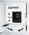
Although the 1973 Tube Stock cab arrangement was developed from the 1972 and C Stock designs, with the desk having air and speedo gauges in the centre and the combined traction/brake controller on the left, there was a significant new development installed to assist drivers with failures. The trains were originally fitted with a train monitoring system called a Fault Annunciator - the initials being FA whether by accident or design. It was intended that all the essential functions of the train would be reported to the FA in the leading cab. This would help the driver to find out which car had a fault and what the fault was.
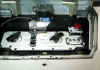
 Fig 12: View of offside of 1973 Tube Stock
cab as refurbished, showing the Train Equipment panel
Fig 12: View of offside of 1973 Tube Stock
cab as refurbished, showing the Train Equipment panel
Click on the image for the full size view.
The original reason for the introduction of the FA, which was quickly renamed a Train Equipment Panel (TEP), was a result of the use of electrical control of emergency braking (ECEB as it is called by LU) and the Westcode brake. The ECEB system uses a round-the-train circuit to perform the safety functions of the brake pipe, monitoring the deadman's handle, passenger emergency handles, tripcocks and train continuity. Train crew had always used the sound of escaping air to detect a brake pipe "burst" or the operation of a safety device, but the new system was silent. A method was therefore needed to advise the crew of where faults were or what device had operated. Thus the FA, sorry TEP, was born.
There was also the need to carry out a brake test. In reality, this was designed to confirm that the brake pipe was complete along the whole length of the train and that an emergency brake could be applied from anywhere on the train and still operate correctly. The test required two persons to do it, one at each end of the train. The TEP on the 1973 Tube Stock was designed to allow the round-the-train brake circuits to be tested and to confirm that brakes applied and released on each car. The test is done from two push buttons in the cab and it is carried out by one person.
The trouble was, the TEP was the first application of solid state control electronics to an Underground train and the system proved very unreliable. It was also too delicate for a maintenance regime based on the application first of oil to anything which did not work and then a two-pound hammer if the oil did not solve the problem. It was also too complicated. The TEP had indications for compressors, lights, brakes, and so on but on and off indications for each too. This was data overload for the driver, who only really needed to know what was wrong, and only when something was wrong. As the data displayed was also often incorrect, drivers quickly lost faith in the system and in the stock, which developed a very poor reputation as a result.
There have been a large number of modifications to the stock since it entered service. Most of these were invisible to the passenger but they were important in trying to improve reliability. The stock has been through at least two series of engineering modifications - one in the early 1980s and one in the 1990s. Also, the original set up for the trains was for two-person operation. The guard occupied the rear cab and controlled the doors from there. The trains were converted to OPO in 1986-7. The conversion consisted of minor switching modifications to the trains but required the installation of train radio and mirrors and CCTV cameras on stations. The 1973 Tube Stock Passenger does not have Passenger Door Control (PDC) or Selective Reopen. These features were not specified for tube trains at that time.
The train now has a modified Train Management System, which replaced the TEP during the period 1992-4, which monitors the operation of only the essential equipment on the train. The TMS box is mounted to the right of the end door and positioned so that the essential elements of the display can be seen by the driver from the driving position. The TMS has a failure display light for each car. If an item of equipment fails on that car, the car light is illuminated together with a light to indicate which item of equipment. There are also isolating switches provided to allow the defective equipment to be switched out of operation. Around the time of the TMS modifications the trains were also equipped with "Correct Side Door Enable" (CSDE), to prevent the train doors being opened on the wrong side of the train. CSDE was introduced on the Piccadilly Line on 6th September 1993.
The door operators were also new. The traditional method of door operation was to provide a pneumatic door engine for each door leaf. This meant that each tube car had 12 door engines. On the 1973 Tube Stock, this was reduced to 8 by pairing up some door leaves to operate off one engine. The two door leaves were connected to the door engine by long links. The arrangement only applied to the doors either side of the longitudinal seating. There was not the space available to do it where the transverse seats were located.
To the Top of this Page
Back to the Rolling Stock Page
Equipment
The 1973 Stock is arranged so that each 3-car unit is self contained. If it is a double-ended unit, it can be driven from either end. The general arrangement of the equipment is shown in the diagram below. On the double-ended units, a Driving Motor Car is used in place of the UNDM.
 Fig 13: Equipment schematic of 1973 Tube
Stock showing simplified layout of systems.
Fig 13: Equipment schematic of 1973 Tube
Stock showing simplified layout of systems.
Click on the image for the full size view.
The 1973 Stock is equipped with DC traction motors using a single, pneumatically driven camshaft for resistance control. The traction circuit is arranged in a classic series-parallel configuration with weak field control. Each of the two motor cars in a 3-car unit has four motors, giving 66% axles motored. The two motors on one bogie are permanently connected in series.
 Fig 14: Original 1973 Tube Stock bogie.
Click on the image for the full size view.
The motors are type LT 118, built by Brush and drive the axle through a gear ratio of 17:75. The low voltage traction control circuits are duplicated and arranged so that one set of control circuits operates one motor car of a 3-car unit, whilst the other set operates the other motor car. This set-up ensures that a low voltage control circuit failure will not disable the train. Only 50% of control will be lost.
The resistance controller camshaft on this stock gave a lot of trouble in its early years of operation, largely because it was a new and untried design. Previous stocks with rheostatic braking used two camshafts, one for series switching and one for parallel switching. In an attempt to reduce space requirements and cost, the two camshafts were combined into one larger and heavier design for the 1973 Tube Stock. The mechanics of the design were not quite up to the job in some areas and there were a lot of modifications to try to get the thing to perform more reliably.
Each 3-car unit has a single Westinghouse 3HC43 air compressor. The double ended units have two compressors. LU has a rule which requires that trains must only be allowed to operate in service with two functioning compressors. The double-ended units can therefore be used as a 3-car train if required. They were used on the Holborn - Aldwych shuttle service in this way until the Aldwych branch was closed in 1994 . Some units which had Hydrovane rotary compressors when first delivered have had these replaced due to their unreliability.
Each motor car has a motor alternator (MA) providing 230 volts AC at 850Hz for auxiliary services. The two MAs on a unit supply half the lighting on the unit, arranged so that all the lights down one side of the train are fed from one end and the other half from the other end. This means that only 50% of the car lights are lost when the motor car supplying the MA passes over a current rail gap. Lighting is supplied at 115 volts AC. The MA recharges the battery on each motor car at 50 volts DC and supplies the control circuits at that voltage. During refurbishment, the trains were also fitted with a static converter on each trailer car to supply a new, ceiling mounted ventilation fan system.
A block of 'A' units are provided with de-icing equipment on the trailer cars. These are numbered 606 to 652, even numbers only. The cars are identified by a blue spot next to the car number. When the de-icing equipment is operating, a blue indicator light on the roof is illuminated.
To the Top of this Page
Back to the Rolling Stock Page
ETT
The 1973 Stock order included two test units equipped with solid state traction equipment and electronic control systems. These were known collectively as the ETT (Experimental Tube Train). The units were numbered 892-692-893 (delivered 1977) and 894-694-895 (delivered in 1979). They were both double-ended units. The first unit was equipped by Westinghouse, the second by GEC. Both were later converted to standard at Acton Works, the first unit entering passenger service in 1987, the second in 1986. The units were converted so as to allow additional spares when the Heathrow loop was opened.
To the Top of this Page
Back to the Rolling Stock Page
Refurbishment
 Fig 15: Trial refurbishment unit 190-590-390
with its specially adapted unrefurbished unit 123-523-323 approaching Acton Town in 1992.
Fig 15: Trial refurbishment unit 190-590-390
with its specially adapted unrefurbished unit 123-523-323 approaching Acton Town in 1992.
Photo by B Hardy
Click on the image for the full size view.
Once it had been decided to refurbish the Piccadilly Line fleet in 1990, a spare UNDM, No 314 was given a trial refit. It was then decided to offer possible contractors a unit for a trial refurbishment. This was done because the refurbishment of the 1967 Tube Stock had taken far longer than expected because the contractors had no idea what they were getting themselves into. By offering a unit as a trial, the contractors got to see what was required and could then make a sensible offer. Metro-Cammell did the trial refurbishment on unit 190-590-390 and this was completed in October 1990. The unit ran in service with standard unit 123-523-323, which was specially adapted to permit operation with the refurbished unit (Fig 14 below). In particular, the door controls were altered to include warning chimes like those on the refurbished unit.
 Fig 16: Production version of refurbished
1973 Tube Stock at Ealing Common, 2002.
Fig 16: Production version of refurbished
1973 Tube Stock at Ealing Common, 2002.
Click on the image for the full size view.
The fleet refurbishment contract was given to RFS of Doncaster and the first two units when there in May 1993. However, RFS was taken over by Bombardier and the refurbishment work was carried out at their factory at Wakefield.
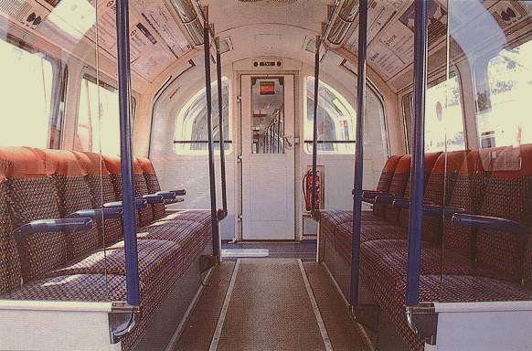 Fig 17: Interior of trial refurbished 1973
Tube Stock without perch seats (Photo by B Hardy).
Fig 17: Interior of trial refurbished 1973
Tube Stock without perch seats (Photo by B Hardy).
Click on the image for the full size view.
The whole of the inside of each car was stripped out and large windows cut into the body ends. Seating was refitted as all longitudinal, reducing the original seating of 44 per car to 38 per car. Perch seats were provided where luggage storage space was available near doorways.
 Fig 18: Luggage space with perch seat next to double
doorway on refurbished 1973 Tube Stock
Fig 18: Luggage space with perch seat next to double
doorway on refurbished 1973 Tube Stock
Click on the image for the full size view.
New covered lighting has replaced the exposed tubes. It looks better but the cars have become duller with age because of dirt and condensation developing inside the covers. The cars have been rewired. A digital voice announcement system has been provided and there are scrolling electronic displays inside the cars over the side windows. The display is so small it can only show the name of the destination station.
 Fig 19: Interior of refurbished 1973 Tube
Stock showing map and electronic sign. The sign is so small only scrolling
destination information is provided.
Fig 19: Interior of refurbished 1973 Tube
Stock showing map and electronic sign. The sign is so small only scrolling
destination information is provided.
Click on the image for the full size view.
 Fig 20: 1973 Tube Stock interior with new
ventilator and lighting covers inside refurbished car.
Fig 20: 1973 Tube Stock interior with new
ventilator and lighting covers inside refurbished car.
Click on the image for the full size view.
New ceiling fans have been installed inside the cars. These are powered by a static converter added under each trailer car and powered of the adjacent DM car. The ceiling fans do not provide air conditioning as there is no space for the equipment inside a tube car and nowhere to dispose of the heat generated inside a tube tunnel.
Drivers cabs have been given air conditioning because of the need to seal the cabs to comply with new noise at work regulations. Cabs have been tidied up and some improvements made to seats and controls (Figs 11 & 12). A new drop down emergency exit in the form of folding steps has been provided at the front "M" door (Fig 21).
 Fig 21: Emergency detrainment steps at end doorway on
refurbished 1973 Tube Stock
Fig 21: Emergency detrainment steps at end doorway on
refurbished 1973 Tube Stock
Click on the image for the full size view.
Back to the Rolling Stock Page
To the Top of this Page or to the Home Page This page upgraded 28 February 2003 Copyright © Tubeprune 2001, 2002, 2003. If you have comments or if you would like to use any part of this site for publishing or commercial reasons, please e-mail me |