Types of Signals on London Underground
London Underground uses a small range of two
aspect signals over most of its lines. They were standardised almost 100 years ago
and have remained little changed since. The basic types are as shown below.
Contents
Standard
Signal Types - Signals on ATO Lines - Signs on ATO Lines - Central Line Signal Identification - Platform Repeaters - X Signals
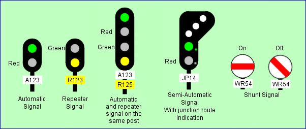
Fig. 1: This diagram of basic types of signals used on London
Underground. The example of the junction signal (JP 14) also shows the side lights
provided to allow the driver to see the aspect when the train is standing close to the
signal. Drivers referred to these as "pig's ears".
A standard signal identification system is used on all lines
except the Central Line. The automatic signal is identified by its plate bearing the
letter A and a number. A repeater signal has a yellow plate and the letter R before
the number, which is the same as the signal it repeats. The repeater is only
used where necessary for sighting purposes. Some locations have a stop signal and a
repeater signal mounted on the same post. It looks like a four-aspect signal but is
actually two separate signals. There will be two identification plates on the signal
post.
An automatic signal shows red or green. On green, the driver
can proceed within the line speed limit or up to the limit of any speed
restrictions. A repeater is simply green or yellow and is only used for advance
warning where visibility of the stop signal is restricted. A junction signal
identifies which route is set by the white light display. No lights over a green
indicates that the main route ahead is set.
To the Top of this Page
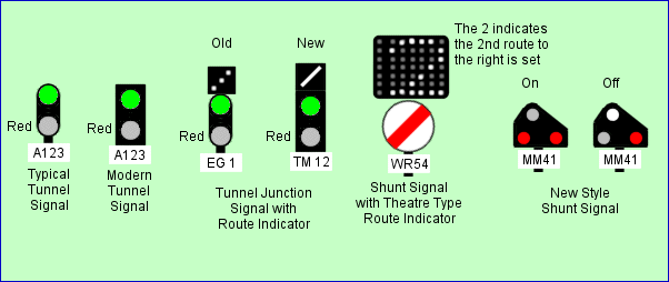
Fig 2: Diagram of various types of signals used on
London Underground including tunnel specific signals and the new type of shunt
signal.
In recent years, some new signals have appeared on London
Underground, like the new type of position light shunt signal which made its debut in
Neasden Depot when it was signalled in the mid-1980s. The new shunt signal looks
similar to the one used on Railtrack but it displays different aspects. Some LU
signals now use fibre optic displays or LEDs in place of lamps.
To the Top of this Page
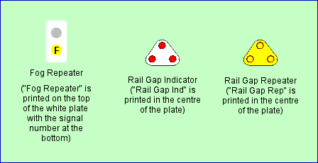
Fig. 3: The diagram above shows miscellaneous types of
signals used on London Underground including rail gap indicators, which illuminate if
traction current is switched off on the section ahead.
London Underground uses fog repeaters in open sections.
They are placed 120 metres in rear of the signal they repeat to provide the driver with a
distance marker in poor visibility conditions. They show the letter F over the
caution aspect. A yellow light indicates that the next signal shows red. A
green repeats the next green. In areas where multiple aspect signalling of the
former standard British Rail type, a white light is provided in place of the green if the
signal ahead shows green, double yellow or single yellow. This type of signalling is
used on the Metropolitan Line north of Harrow-on-the-Hill.
To the Top of this Page
The Victoria and Central Lines are equipped with ATO
(Automatic Train Operation). Some of the signals used on these lines are different
from those used on other lines. For a full description of ATO go to Victoria Line ATO or Central Line ATO.
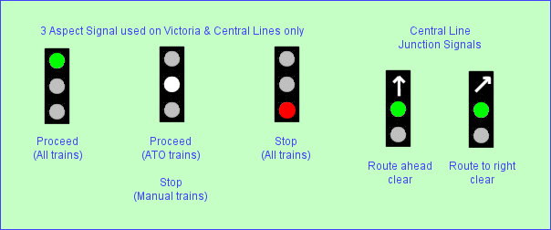
Fig. 4: On a manually driven railway, the
driver relies on visual signals to indicate the state of the road ahead. On an ATO
railway, visual signals are not normally needed except at junctions (to indicate the route
set) and at stations to tell staff if the train can proceed. To allow manually
driven trains to run on an ATO line, 3-aspect signals are provided. These have the
usual red (stop) and green (proceed) aspects and an additional white aspect. The
white aspect allows an ATO train to proceed but a manually driven train must stop until a
green is displayed. The green indicates that the line is clear to the next visual
signal.
On the Central Line, the route indicators on
junction signals (Fig. 4 above) are of a type new to the Underground. An arrow is
illuminated to show the direction of the route cleared, even for main or straight ahead
routes, which were formerly only plain green.
To the Top of this Page
Fig. 5: Because the entrances to blocks on ATO lines
are not always marked by visual signals, markers are placed there. One the Victoria
Line they are known as Headway Posts, while on the Central Line they are called Block
Marker Boards. On the Victoria Line, Headway Posts only occur in automatically
signalled areas, whereas on the Central Line they can also occur in controlled
areas. The Central Line marker boards show the area code as well as the block
number. In automatically controlled (auto) areas, the letter A precedes the number.
On the Central Line, as shown above, the entrances to depots
are provided with marker boards to show where the ATO system starts and finishes.
To the Top of this Page
 Fig. 6:
Signals on the Central Line have new types of identification plates as shown in the
diagram above. They are square and contain a more detailed identification system
than on other lines. Even automatic signals are grouped into areas and given code
letters, usually indicating the location of the signalling equipment room from where they
are controlled. Fig. 6:
Signals on the Central Line have new types of identification plates as shown in the
diagram above. They are square and contain a more detailed identification system
than on other lines. Even automatic signals are grouped into areas and given code
letters, usually indicating the location of the signalling equipment room from where they
are controlled.
There are no repeater signals or X signals on the Central
Line.
Information updated by Bob Yeldham.
To the Top of this Page
To allow platform staff to see the aspect of the station
starting signal, which is usually hidden from view when standing on the platform, most
platforms are provided with platform repeater signals. These are un-numbered and
simply show yellow (to indicate the starter is red) or green. Platform repeaters
will also display repeats of shunt signals and junction indications if these are present
at the starting signal.
 This photo (Fig.
7) shows the platform repeater and starting signal in the tunnel at Moorgate
(Northern). The starter is green and the train is about to leave. This photo (Fig.
7) shows the platform repeater and starting signal in the tunnel at Moorgate
(Northern). The starter is green and the train is about to leave.
Click on the image for the full size view.
To the Top of this Page
Where provided, an X signal is normally the last
automatic signal before a controlled area and must be treated as if is was a controlled
signal. Some X signals aren't always permanent. Some X signals have an
illuminated 'A' to indicate that the area or control has been switched to automatic
operation by a "king lever" in the signal box. This type of signal can be
treated as an automatic rather than applying the semi-automatic rules normally required
for an X signal.
There are some X signals installed for specific
purposes. A floodgate X signal protects floodgates if these are closed in a tunnel,
e.g. Moorgate, Embankment, Pimlico. They are identified according to their line as well as
their number. Thus, what would have been an ordinary automatic on the Northern line, A122,
renumbered to protect a floodgate becomes FNX122, the F for flood, the N for Northern,
then the X. Under normal conditions the signal will have an associated illuminated A
telling train operators it can be treated as an automatic signal if it remains at danger.
Possession X signals are used to protect
sections of track for engineering works, where it is necessary to maintain automatic
signals at danger. To ensure the signal is treated as a semi-automatic, it is necessary to
change the identification plate. The A on the identification plate is replaced with PN
indicating its use to protect a possession, followed by the letter X. When
the track work is completed the signal identification plate is replaced with the original
A and the signal is returned to normal working.
Track Renewal X signals are used where longer
term engineering works take place and a crossover has been installed to permit movement of
trains on what is normally a straight line. Since local signals will be automatic,
it is necessary to protect the crossover during use. To that end, the protecting
signal is changed, its A replaced by a TR to denote track renewal and an X to denote that
it must not be passed at danger without authority. The signal will usually have an
illuminated A sign for use during traffic hours, during which time the emergency crossover
will not normally be used and train operators can revert to treating the signal as
automatic.
 The photo on the left (Fig.8) shows a Track Renewal Signal at
Westbourne Park (EB), courtesy of Tube Troll. The photo on the left (Fig.8) shows a Track Renewal Signal at
Westbourne Park (EB), courtesy of Tube Troll.
Click on the image for the full size view
and description
|